Material | Assembling | Firmware | Finishing
A fun project to build your own custom keyboard without spending a fortune!
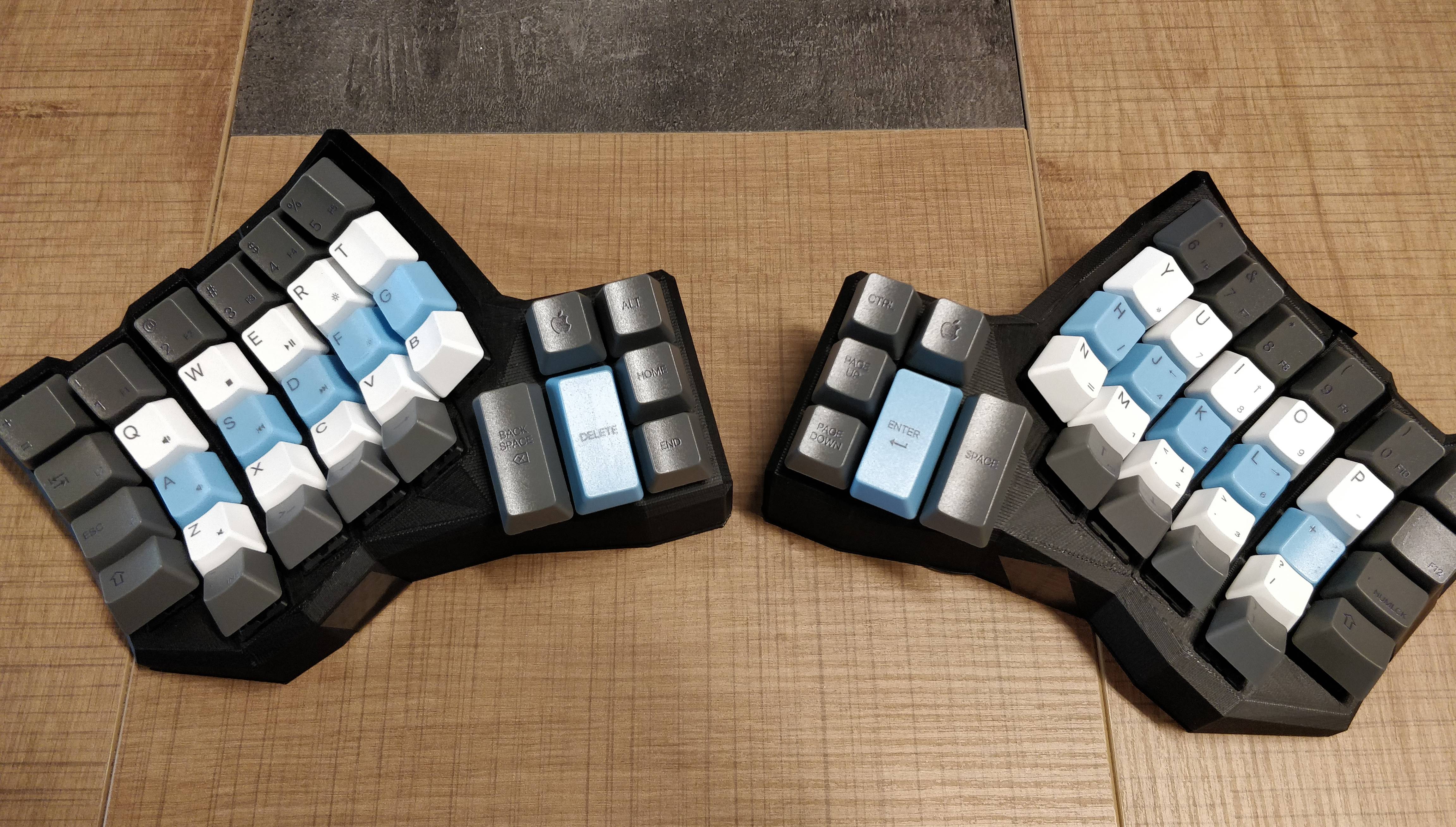
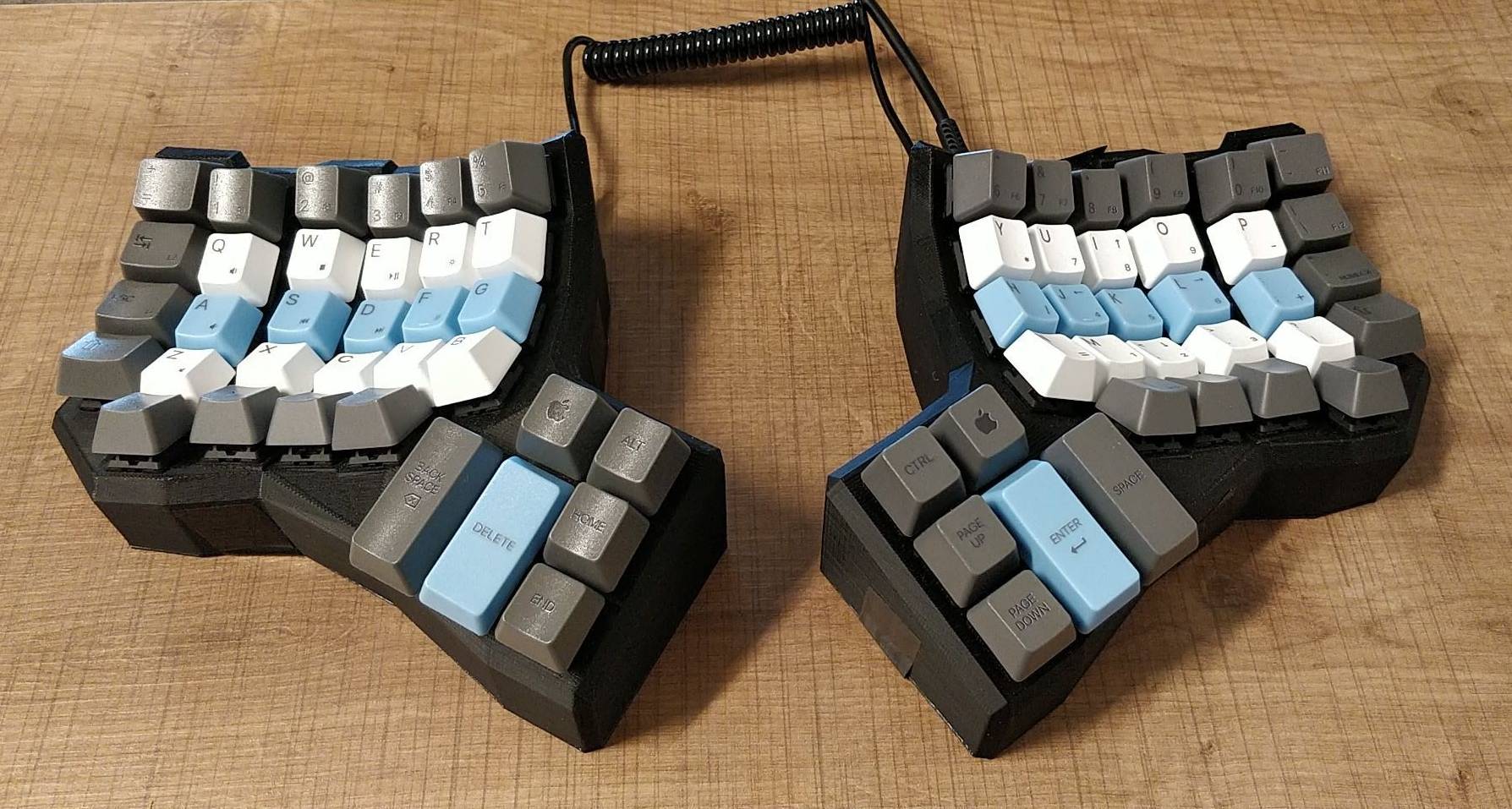
A few tips to complete the various guides available on the Internet, to fill the gaps of what was not clear to me when assembling my Dactyl-CC. This guide will not include the entire process of wiring and assembling because this is very well covered in the link belows.
How long did it take?
At the beginning, I have spent quite some time to figure out what I needed to buy. Honestly, I went maybe too fast reading the various guides and I made some mistakes (wiring). It is a good idea to first fully understand the need of each component :) After a few evenings and thanks to the tips of my friend Pedro who built the same keyboard before me, it took me:
- about 3/4 weeks to order and receive all the components
- about 2 full days to assemble it
- another day to fix assembling mistakes :)
Since this was a fun side project, outside my working hours, I was not in a hurry. It has been actually a great hobby during the confinement period that happened in France in 2020 because of the COVID pandemic.
In the end, it took me 2/3 months and I have spent about ~100 EUR, or slightly more, in material.
Let's start!
The first reference link that you need to often get back to is the guide from Michael Johns: A Dactyl like 3d printed keyboard written in C++. This also because you can find there the STL files to 3D print the case. If you are like me and you don't know much about 3D printing don't worry, I will share a few tips below :)
The second super useful guide is Building a Dactyl Keyboard, Running QMK (which is recommended in the one above). I do recommend to read it carefully because it contains many tips and lesson learned. WARNING: do not follow exactly the cabling of the thumbs cluster as described there. That guide is for a Dactyl keyboard which has a slightly different thumbs cluster. I did that mistake and after programming the firmware I realized the issue and I had to fix the cabling (more on this below).
Similarly to this second guide, you can find here another similar one with some nice pictures and a schema of the audio jack, very useful!
Below the list of components that I bought to assemble the keyboard.
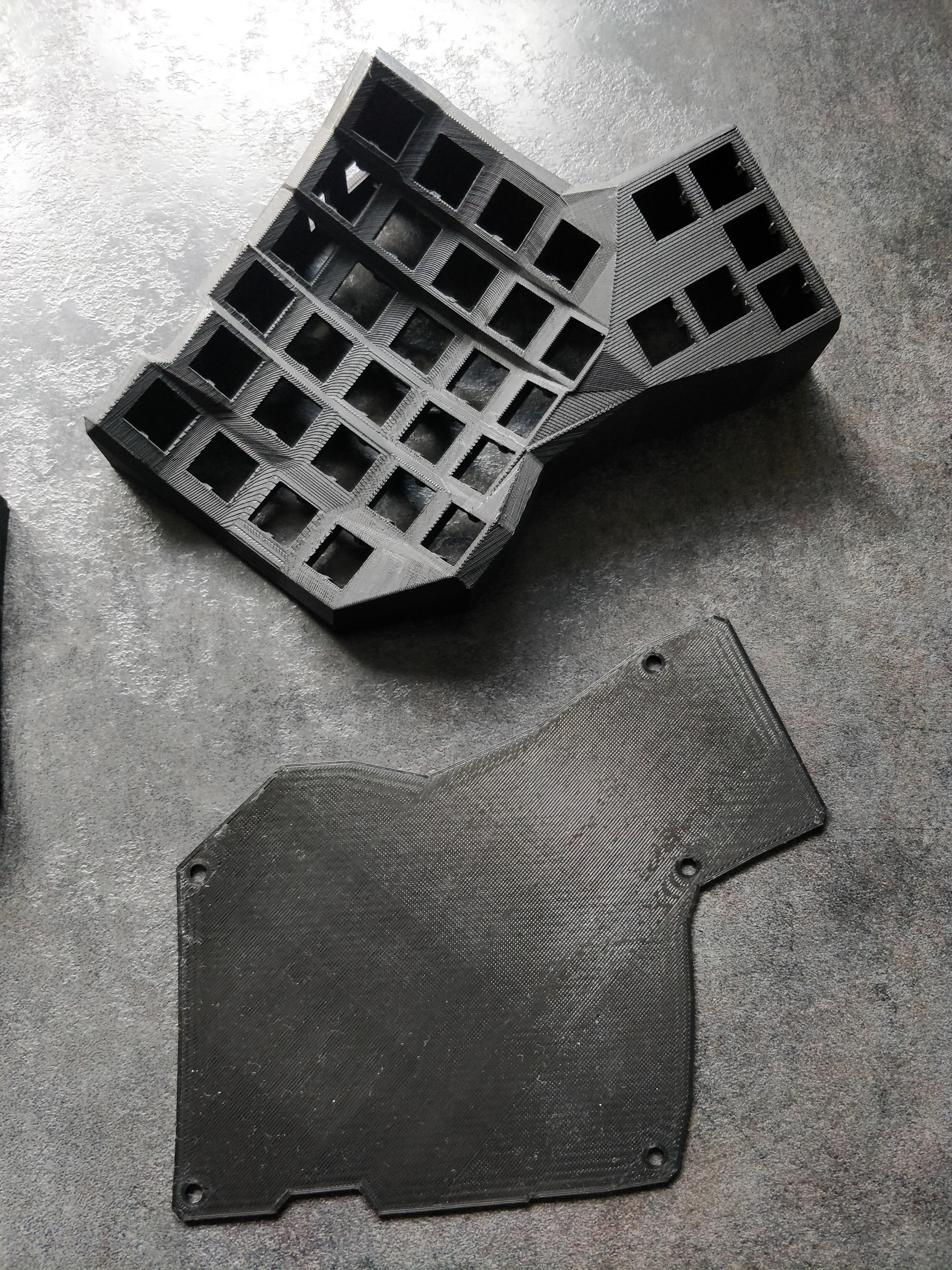
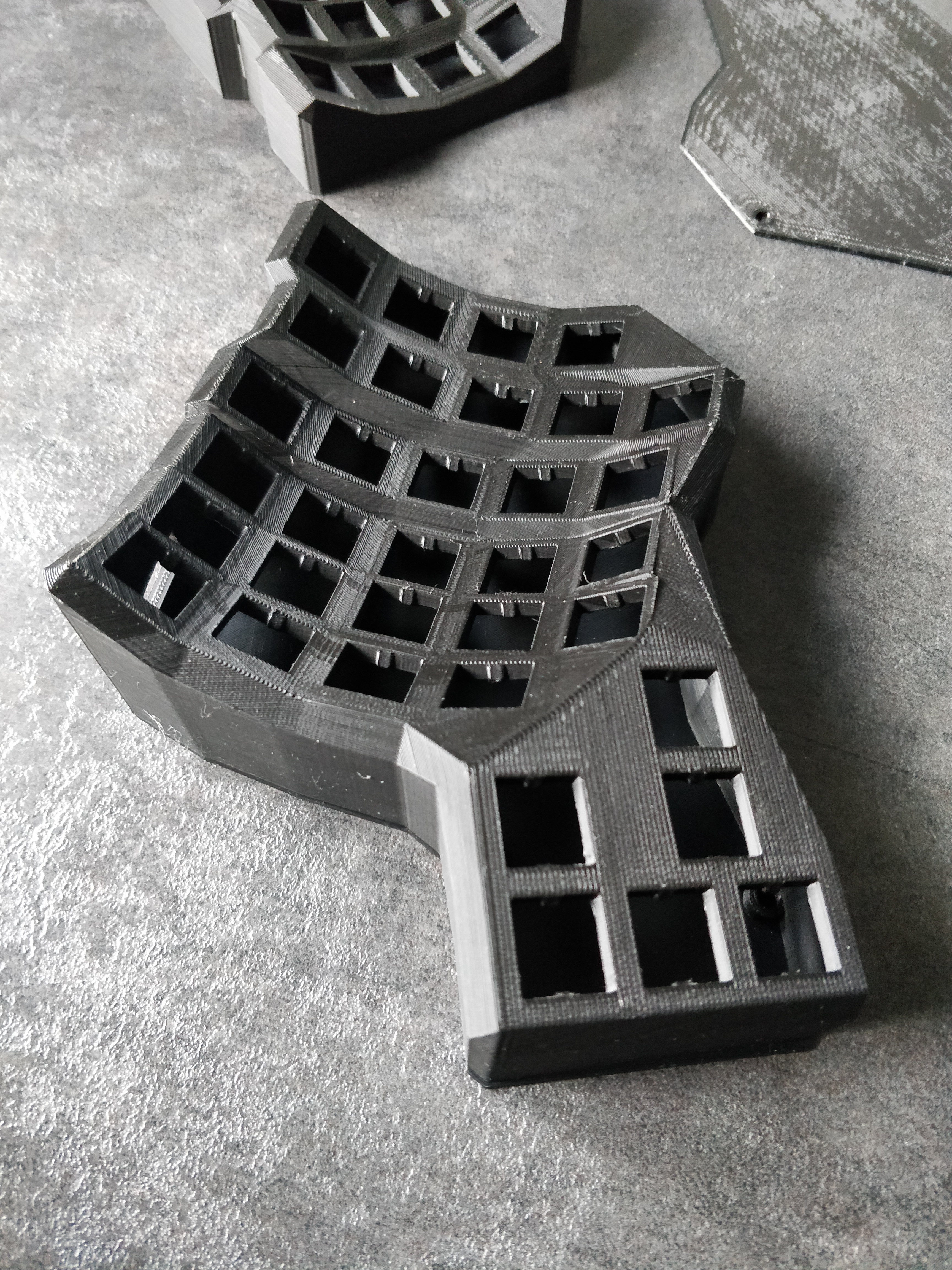
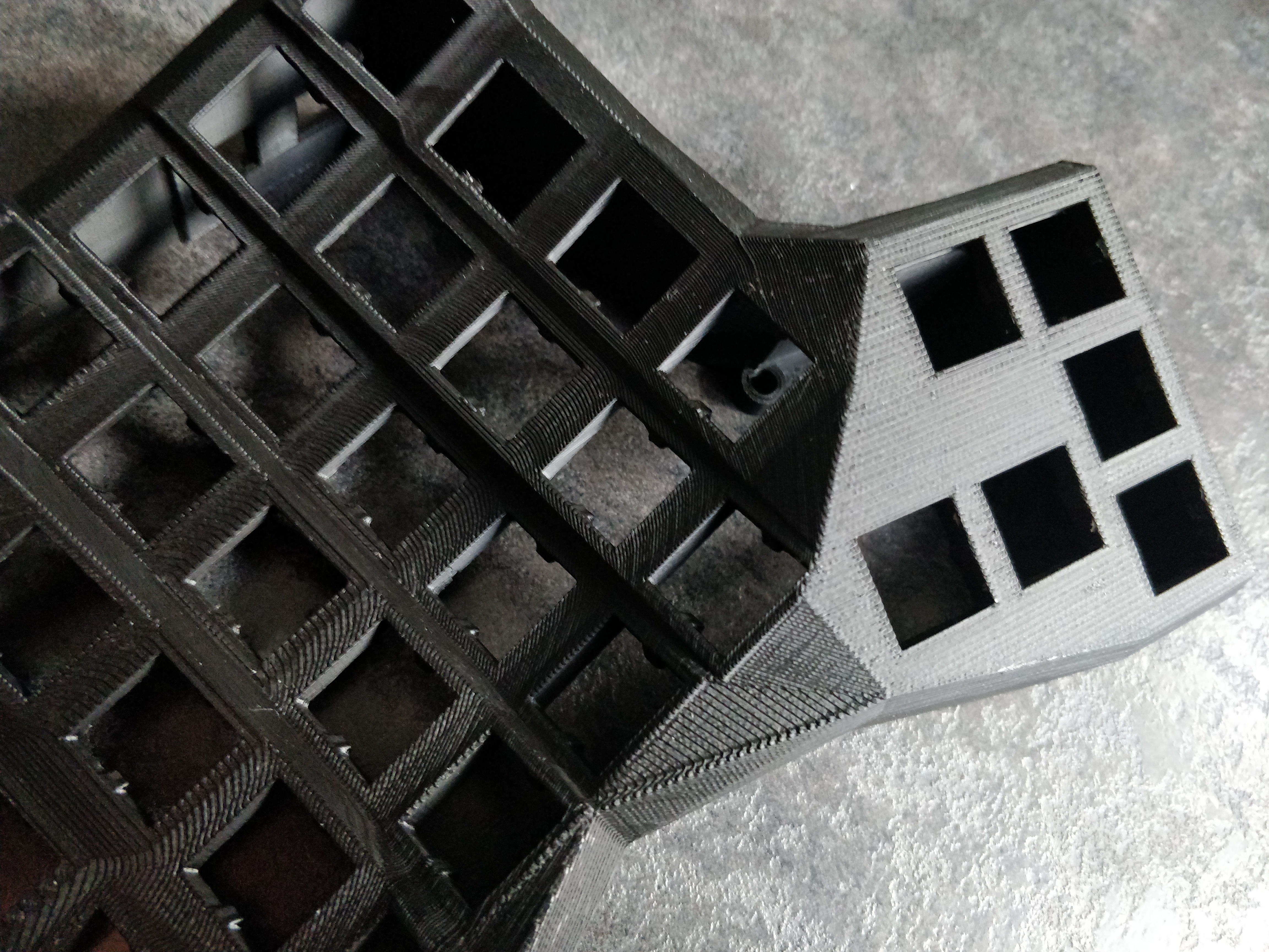
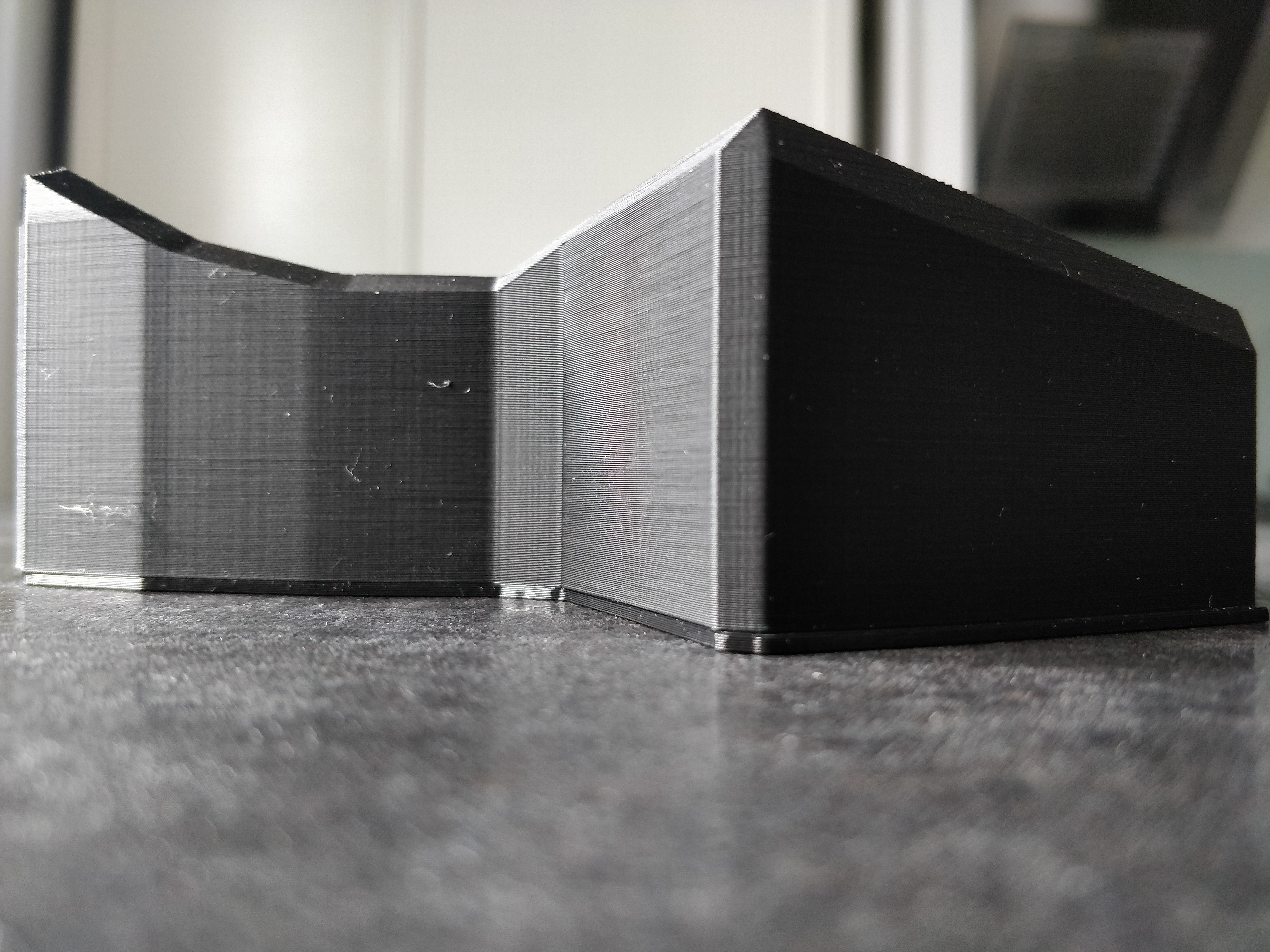
I have used the STL files kindly shared by mjohns that you can find in his repo. I think that they are great: the size of the case is perfect and the key switches are well blocked when inserted in each hole, they don't move.
I only found a bit hard to find a solution to close the bottom part of the case and to block the audio jack and USB connector, more on this later.
The hardest part was to get up to speed with 3D printing and different materials. I have watched lots of videos that explain the differences between materials to try to understand what was the most adapted for such project and to avoid to spend a fortune. I have also compared a few online website that 3D print things and in the end the best for me was CraftCloud.
- Material: PLA
- Color: Black
- Finishing: Standard
- Infill: 20%
Basically I went for all the default and cheapest settings and I have to say that I am very happy with the result: the case is very solid, rigid, even the smallest parts, for example the small parts that blocks the key switches. I am also quite satisfied with the finishing, it looks brushed.
- 1 x Teensy 2.0: a microcontroller that where you will load the keyboard firmware and you will wire all keys. Will be in the right part of the keyboard and it will communicate with the left part via the audio jack.
- 1 x MCP23018: you will wire it to the keys of the left part of the keyboard and it will communicate with the Teensy via the audio jack.
- 1 x 28-pin DIP socket [OPTIONAL]: I have soldered all the cables to this socket and then plugged in the MCP. In this way you are sure not to overheat the MCP and you can eventually replace the socket in case of mistakes or damage.
- 68 x 1N4148 diodes: one per key switch, order a few spare ones because it is easy to do mistakes.
- 2 x 2.2K resistors: both wired to the audio jack on the right part, which is wired to the Teensy.
- 2 x TRRS Jack female: they will be wired in each side of the keyboard. Make sure that you buy TRRS ones, with 4 connections pins.
- 1 x TRRS Cable (male - male): cable to connect the 2 sides.
- 2 x TRRS extension cables (female - male) [OPTIONAL]: I have bought the shortest extension cables that I have found because the audio jack wiring is quite delicate and when plugging/unplugging the audio cable I broke multiple times the connections. With the extensions, I have glued the audio jack to the case so that it won't move and the audio cable will instead be plugged to the extensions.
- 1 x USB Mini-b male to USB b/c female: this needed to plug your keyboard to your PC. The Teensy 2.0 connection is a mini-b and you can choose the female connector.
- Spool of colored wire: it is suggested in many guides to use wire with 8 colors 30AWG. Honestly it is very thin and it will break many times while wiring but it is the right size when soldering all of them on the Teensy or MCP.
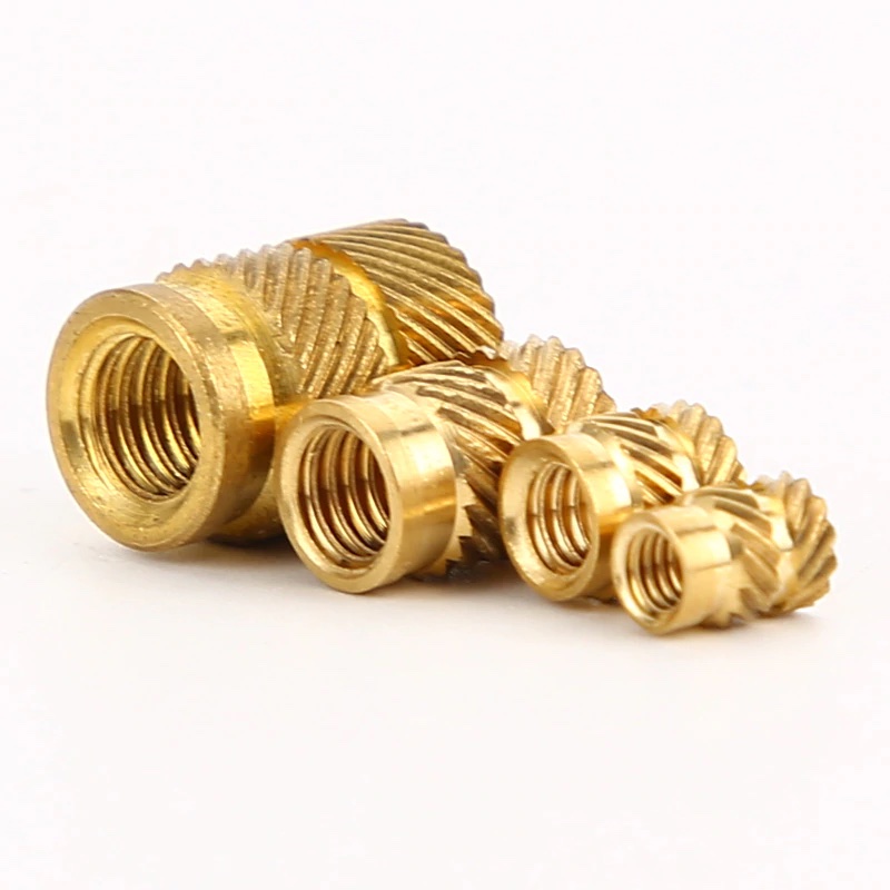
- M2.5 screws and brass nuts: I didn't find a better solution at the moment than fix the brass nuts in the case holes with some glue.
Soldering iron with a small tip, small tongs/nippers and hot glue are also very useful.
Switches is easy: just order 68 switches as you like them. I have ordered the classic Cherry MX Brown.
Keycaps is a different story :)
I wanted the same keycaps as the Kinesis Advantage. If you are lucky, or leaving in the US and not in Europe like me (at least in 2020), you can order the set from them. Otherwise, you will probably need to order a custom set. I did from WASD Keyboards.
Here the steps I followed:
- Understand what I needed. Since the Kinesis has many different keycaps shapes (e.g. for each row), I needed to match its keycaps to a standard keyboard. Here the keycap replacement chart for
WASD Keyboardskeycaps. The 105-Keys classic ISO keyboard has all the necessary shapes: there is only one little difference with the shape of theENTERkey, but it is good enough. - Choose a style: here my final layout.
- Order the set of
105-Key ISO Custom Cherry MX Keycap Set. Here my SVG layout for theWASD KeyboardV2 Designer tool. The trick was to pay attention to the shape of the keycaps in the thumbs cluster and order them correctly.
I have followed this guide and this guide.
My mistake here was to blindly follow the rows/columns colors, in particular also wiring the red column (only one key): with that wiring, the default available QMK firmware configuration was not corresponding to the wiring. As result, these keys were not working. More details below.
I started by installing the keys (without keycaps) in the case. Then all the diodes.
The diodes have a direction, so it is important to pay attention when soldering. I have prepared all 68 diodes twisting the little metal segment to form a little hole, so that it was then easy to anchor the hole to the little pin of each key and solder.
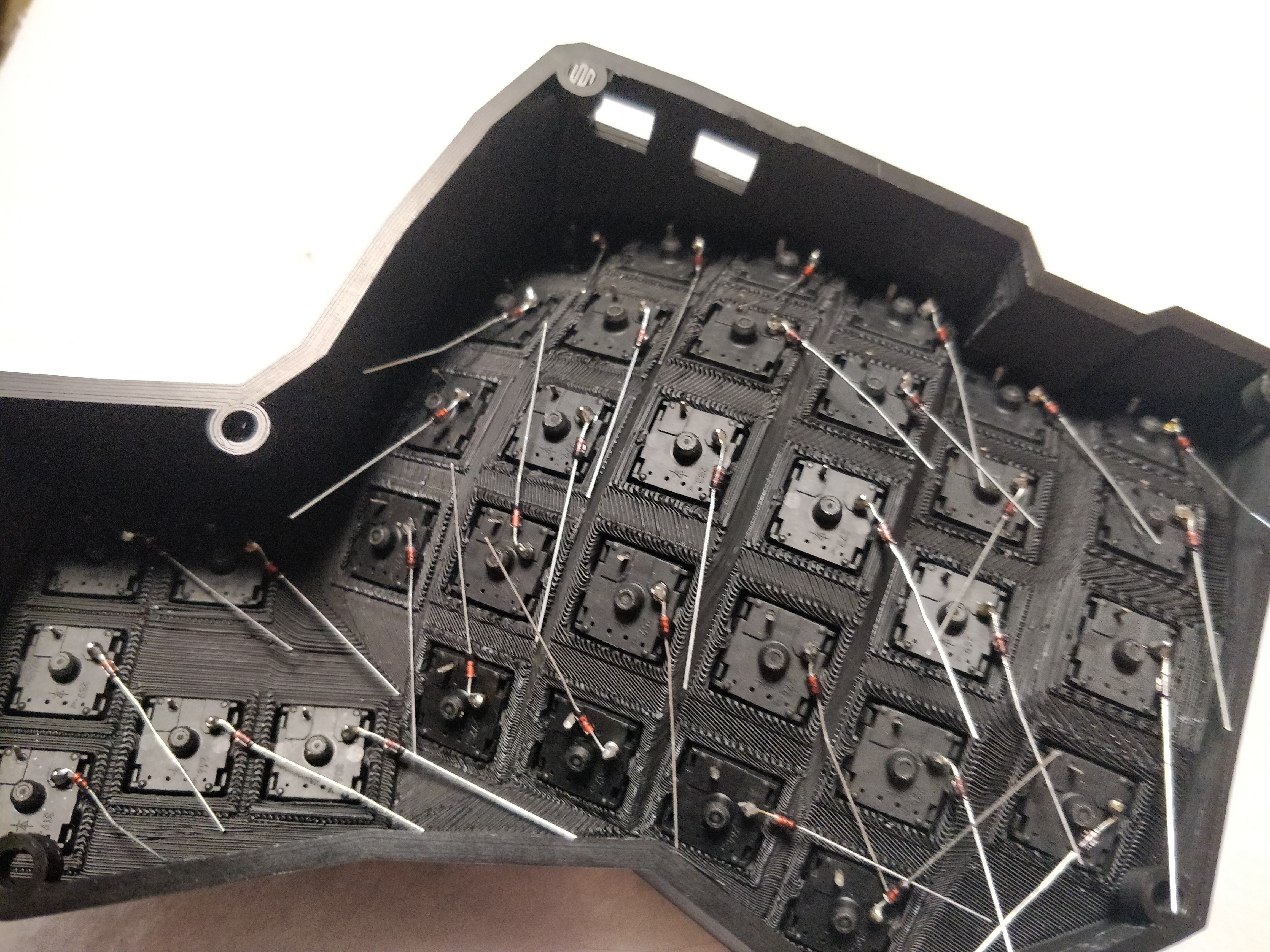
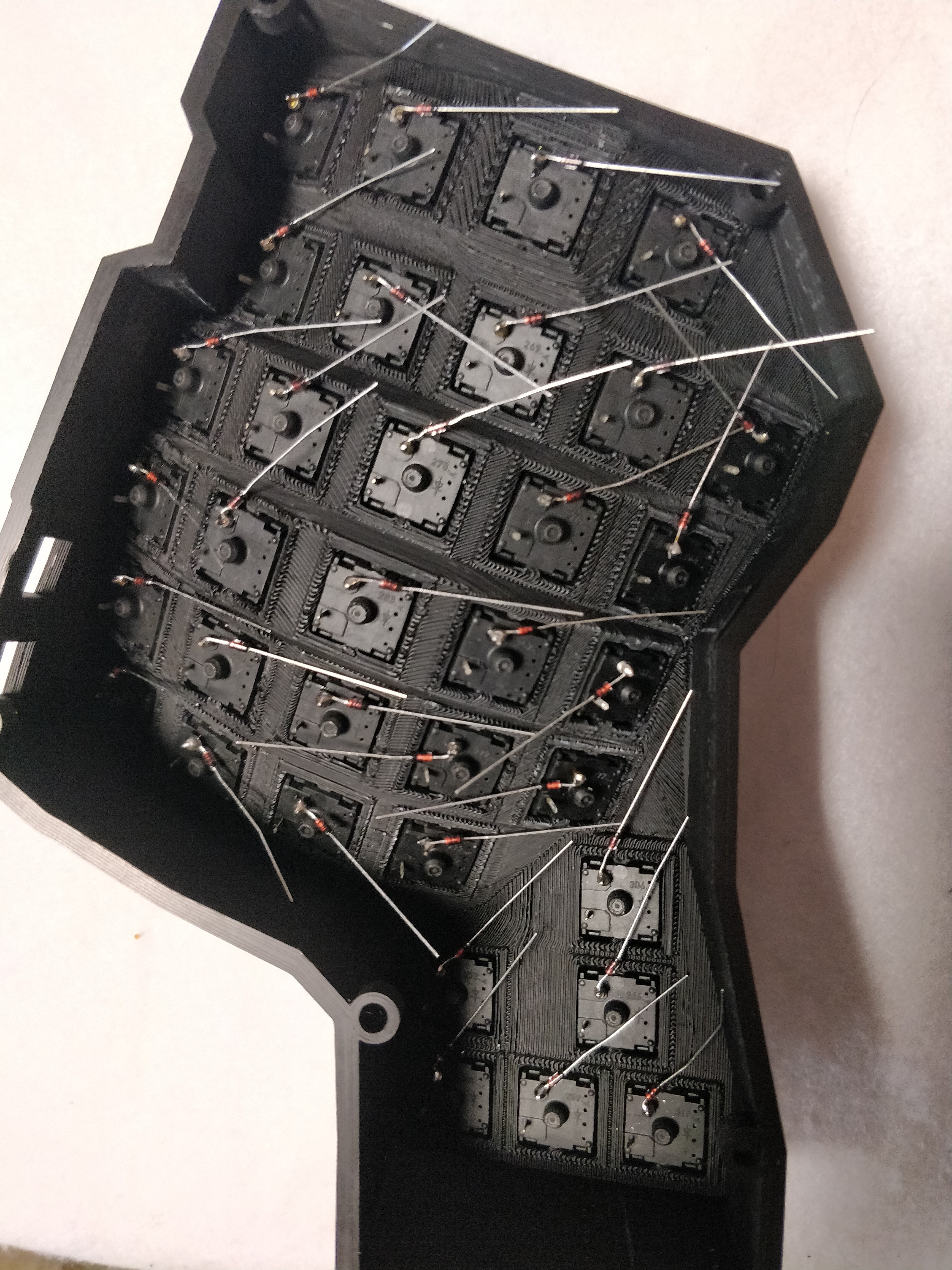
Wiring was rather easy: I followed the same color codes in the schema in the guides and patiently wired rows and columns. I have found easier to prepare the wire before soldering, I had more space than inside the case. I also kept the last segment of the wire that will be soldered to the Teensy/MCP very long, because I was not sure where/how I wanted to install the Teensy/MCP.

Here how it looked at the end, with the mistake of the red column (which I had to change at the end). Unfortunately I forgot to take pictures with the final wiring.
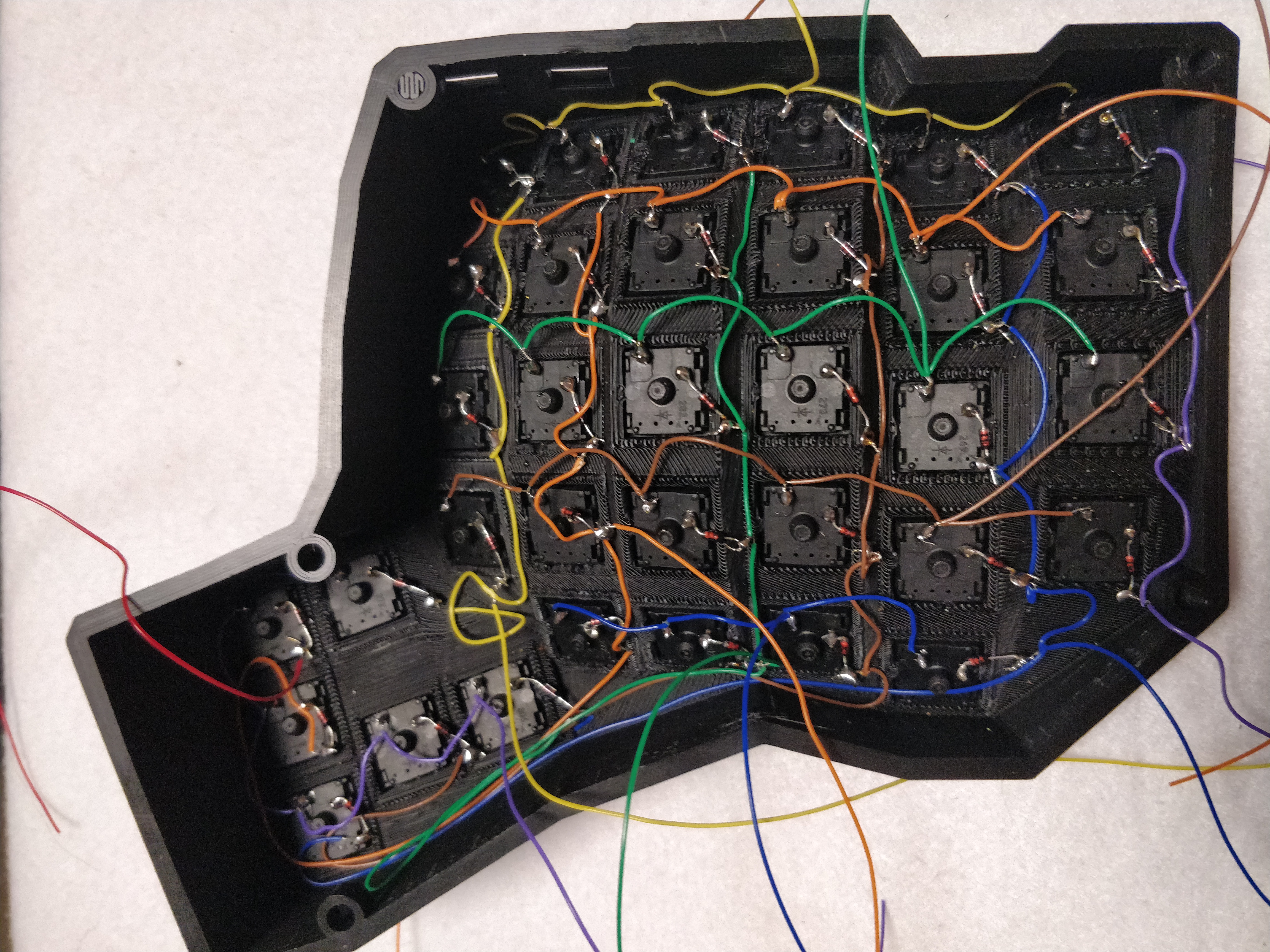
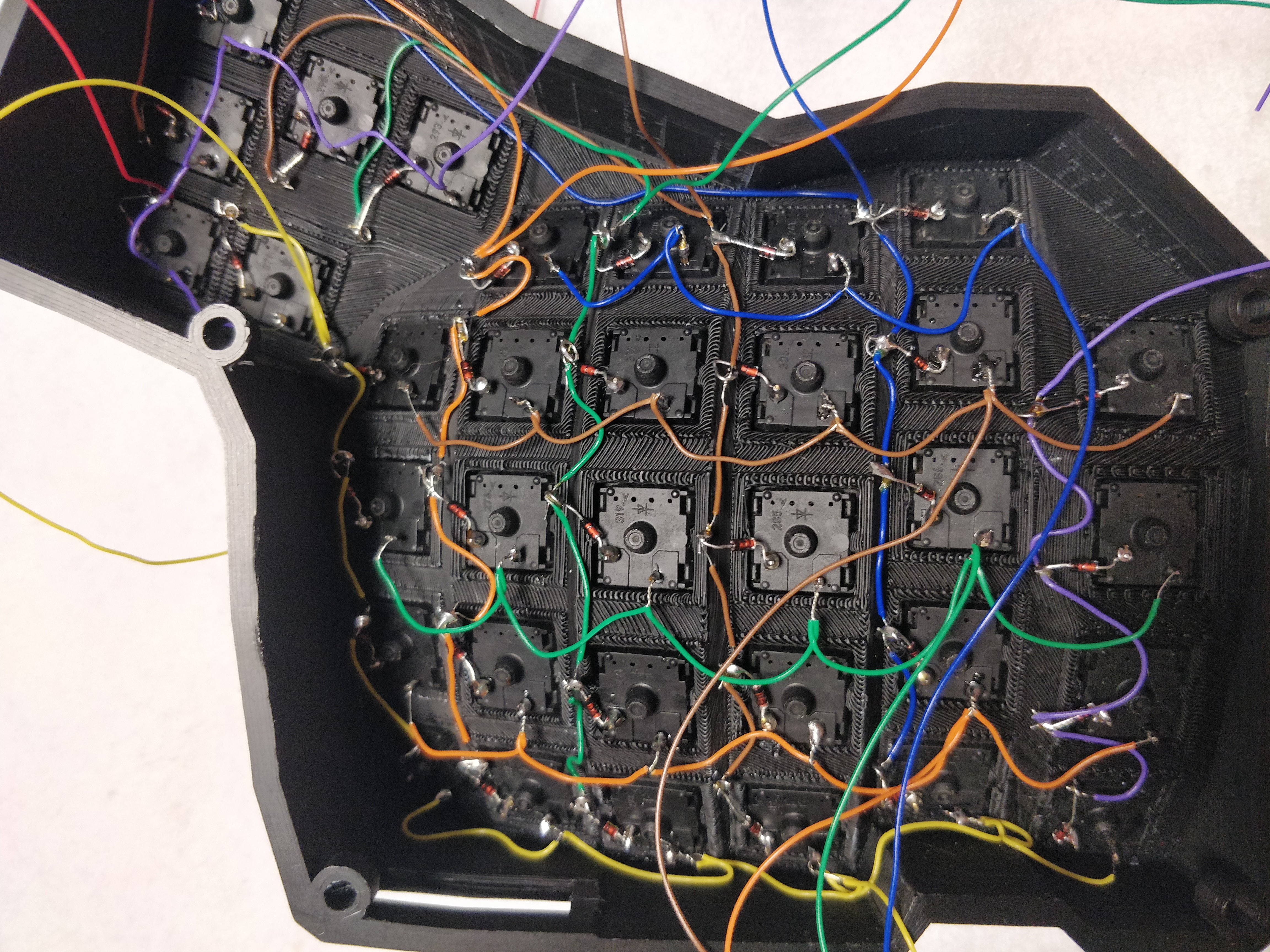
At the end, I have soldered each row and column to the Teensy/MCP and also the audio jack with the resistors.
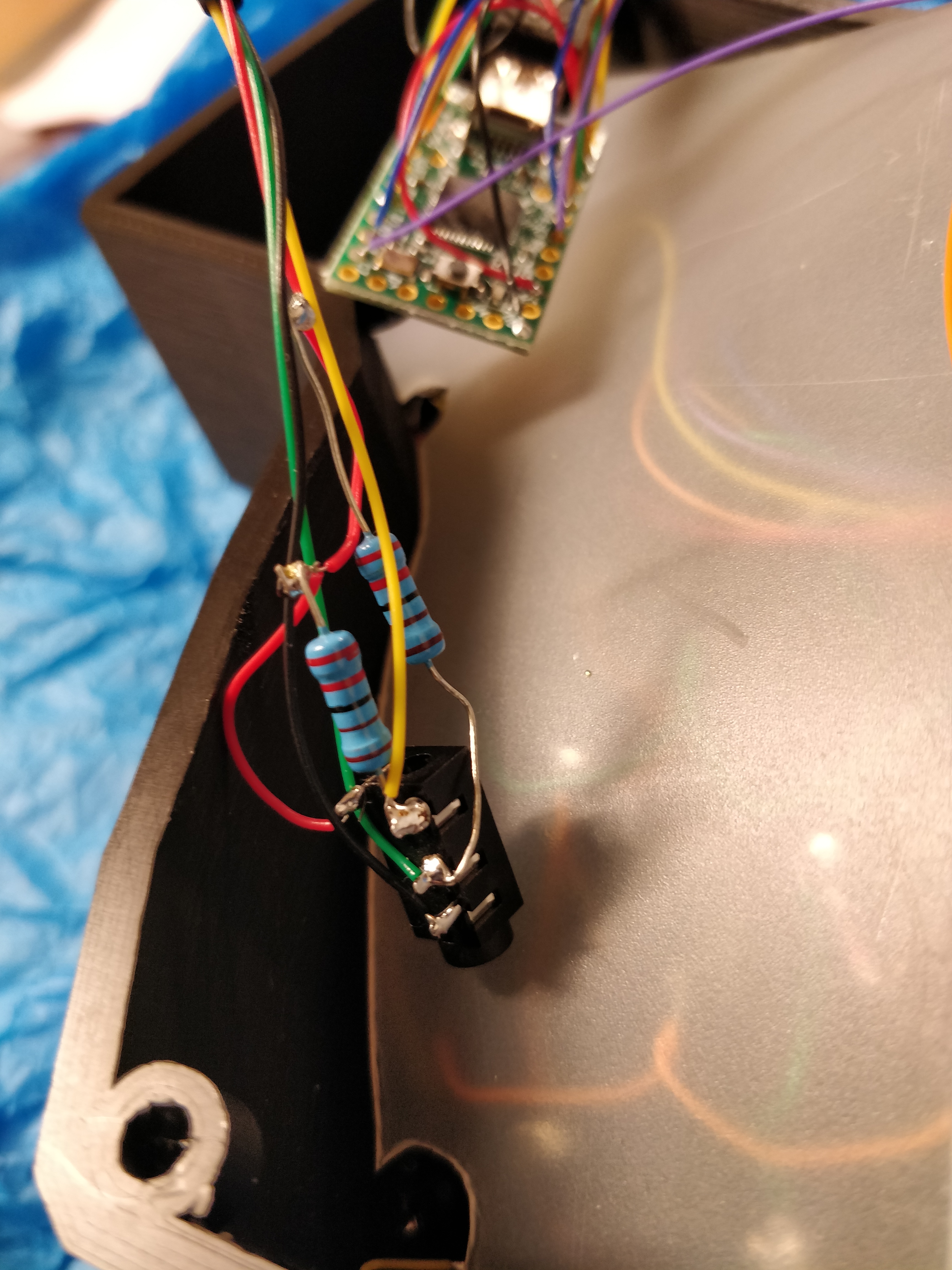
For the Teensy/MCP, I wanted to use the default firmware handwired/dactyl, without any manual customization (only via the online editor, more details below).
Here the configuration for the Teensy/MCP:
#define MATRIX_ONBOARD_ROW_PINS { F0, F1, F4, F5, F6, F7 }
#define MATRIX_ONBOARD_COL_PINS { 0, 0, 0, 0, 0, 0, B1, B2, B3, D2, D3, C6 }
Here the configuration for rows/columns:
/*
 *   LEFT HAND: LINES 38-45
 *  RIGHT HAND: LINES 47-54
 */
#define LAYOUT_dactyl(                                                  \
                                                                        \
    k00,k01,k02,k03,k04,k05,                                            \
    k10,k11,k12,k13,k14,k15,                                            \
    k20,k21,k22,k23,k24,k25,                                            \
    k30,k31,k32,k33,k34,k35,                                            \
    k40,k41,k42,k43,k44,                                                \
                            k55,k50,                                    \
                                k54,                                    \
                        k53,k52,k51,                                    \
                                                                        \
            k06,k07,k08,k09,k0A,k0B,                                    \
            k16,k17,k18,k19,k1A,k1B,                                    \
            k26,k27,k28,k29,k2A,k2B,                                    \
            k36,k37,k38,k39,k3A,k3B,                                    \
                k47,k48,k49,k4A,k4B,                                    \
    k5B,k56,                                                            \
    k57,                                                                \
    k5A,k59,k58 )                                                       \
                                                                        \
   /* matrix positions */                                               \
   {                                                                    \
    { k00, k01, k02, k03, k04, k05,     k06, k07, k08, k09, k0A, k0B }, \
    { k10, k11, k12, k13, k14, k15,     k16, k17, k18, k19, k1A, k1B }, \
    { k20, k21, k22, k23, k24, k25,     k26, k27, k28, k29, k2A, k2B }, \
    { k30, k31, k32, k33, k34, k35,     k36, k37, k38, k39, k3A, k3B }, \
    { k40, k41, k42, k43, k44, KC_NO, KC_NO, k47, k48, k49, k4A, k4B }, \
    { k50, k51, k52, k53, k54, k55,     k56, k57, k58, k59, k5A, k5B }, \
   }
For the wiring for the thumbs clusters, I followed the configuration of the firmware above without the extra red color.
I have also added a plastic separation to avoid any possible short-circuit.
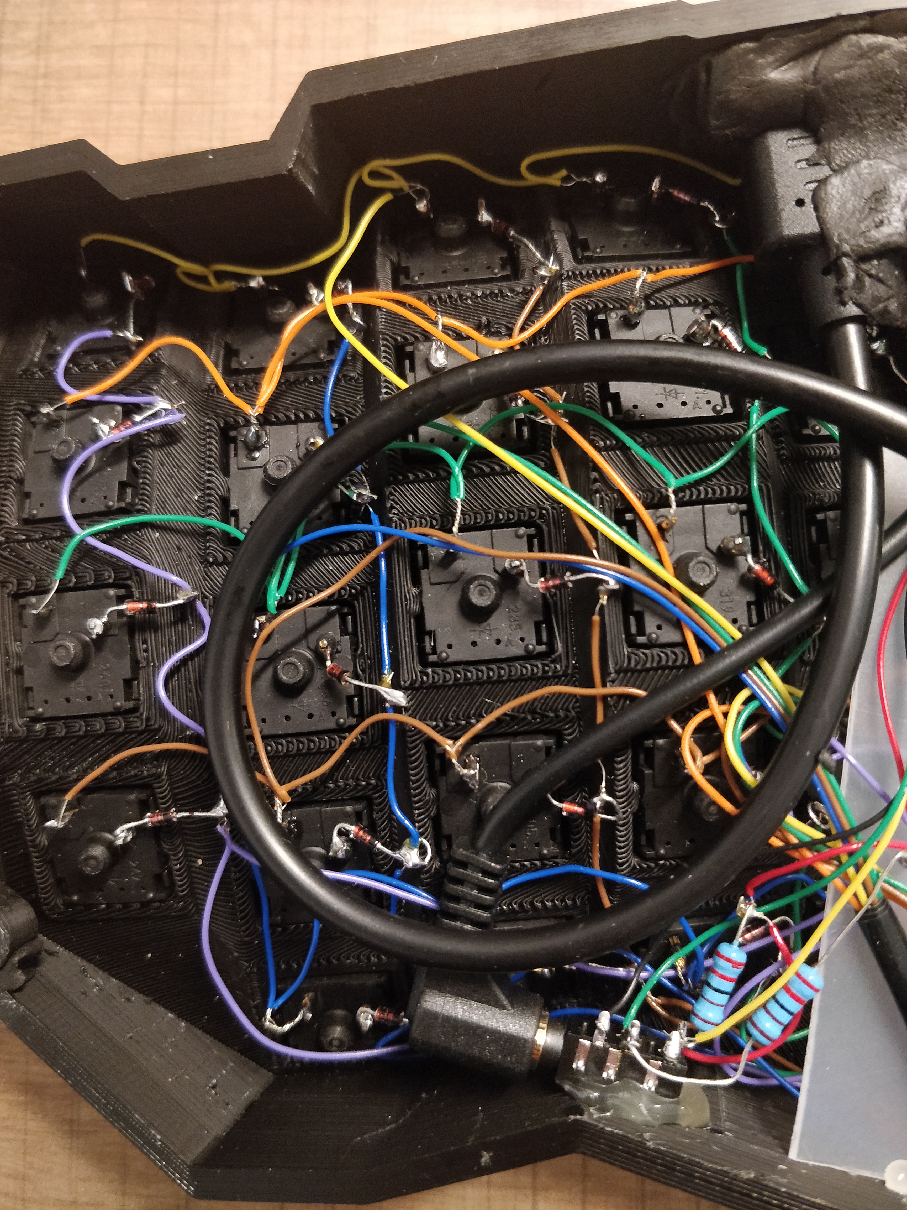
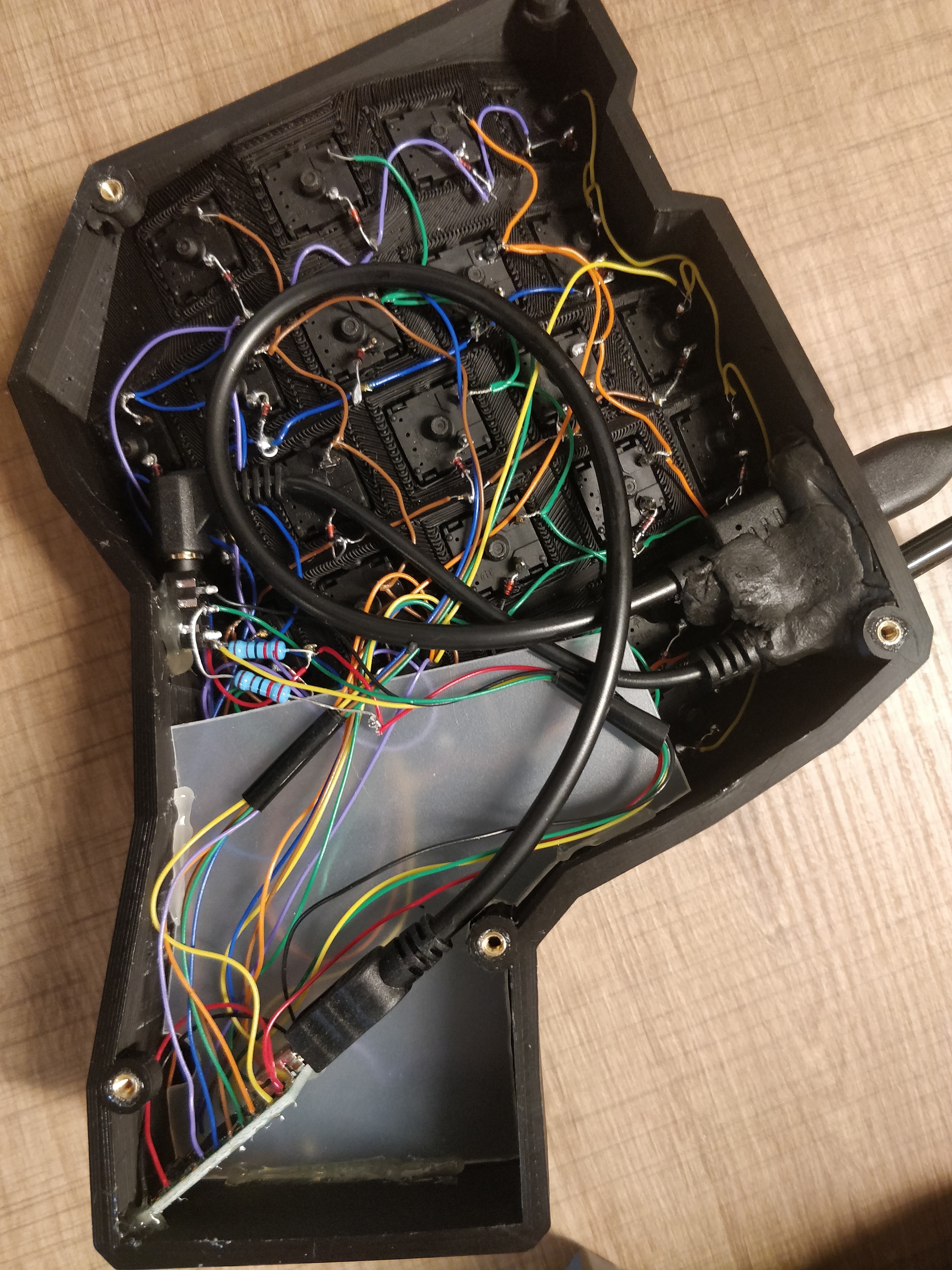
Note: while soldering and moving components around, many segments got cut or disconnected, I had to fix them multiple times.
I used a digital multimeter to make sure that the connections of each row and column were working correctly.
I tested the signal by holding a tip of the multimeter on the first key of the row/col and the other tip on the Teensy/MCP.
I also tested each key and diode using the diode mode in the multimeter and by holding the first tip on one pin of each key and the other tip after the diode soldered on the other pin. When pressing the key, the meter should emit sound. Switching the meter's tips should not.
I have configured my keys using the QMK configurator, starting from the handwired/dactyl layout.
I have simply compiled and downloaded the firmware from the configurator and flashed the Teensy.
Here my firmware.
I used some Sugru to fill the holes and block the USB/Audio ports to give it a more solid look and to avoid that the little wires get cut when plugging/unplugging the cables.
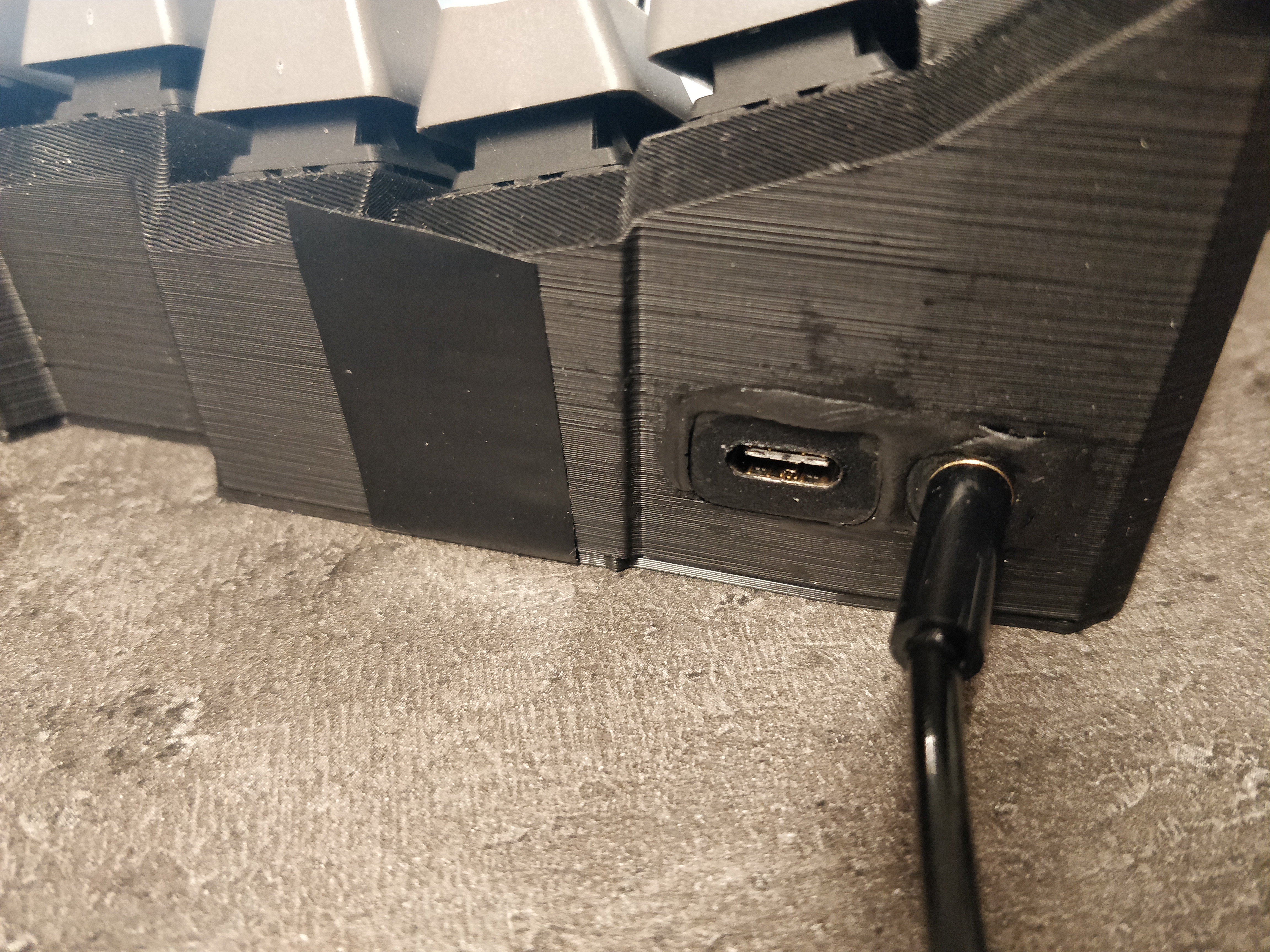
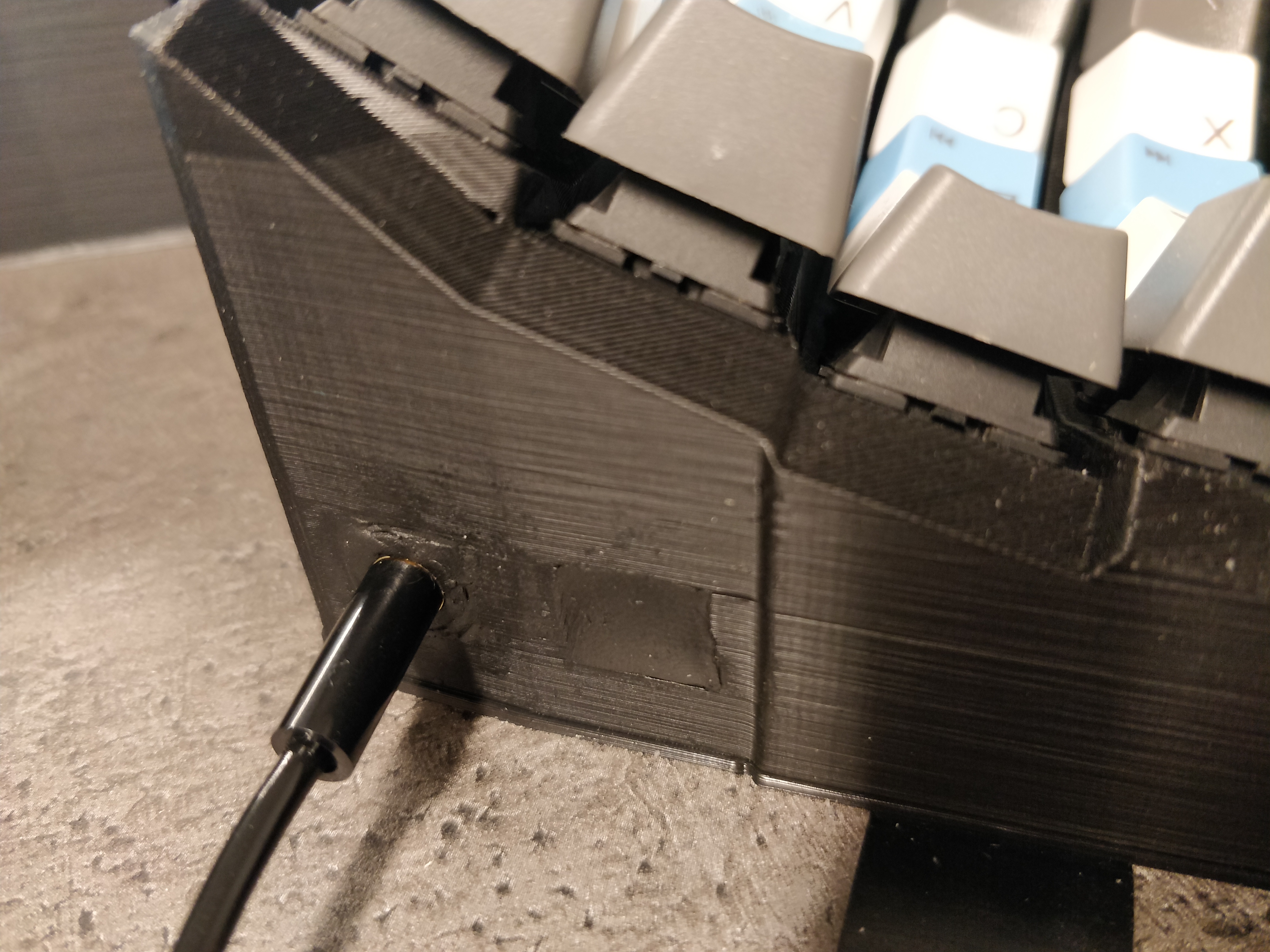
The result is quite satisfying.
